ADRF5717
推荐新设计使用Silicon Digital Attenuator, 2-Bit, 1 MHz to 30 GHz
- 产品模型
- 2
产品详情
- Ultrawideband frequency range: 1 MHz to 30 GHz
- Attenuation range: 16 dB typical steps to 48 dB
- Low insertion loss
- 1.5 dB to 8 GHz
- 2.0 dB to 18 GHz
- 2.8 dB to 30 GHz
- Attenuation accuracy
- ±(0.20 + 2.3% of attenuation state) dB typical up to 8 GHz
- ±(0.30 + 3.2% of attenuation state) dB typical up to 18 GHz
- ±(0.30 + 6.5% of attenuation state) dB typical up to 30 GHz
- Typical step error
- ±0.8 dB typical up to 8 GHz
- ±1.3 dB typical up to 18 GHz
- ±3.3 dB typical up to 30 GHz
- High input linearity
- P0.1dB insertion loss state: 30 dBm typical
- P0.1dB other attenuation states: 30 dBm typical
- IP3 insertion loss state: 51 dBm typical
- IP3 other attenuation state: 49 dBm typical
- High RF power handling
- Input at ATTIN and ATTOUT
- 30 dBm typical steady state average
- 33 dBm typical steady state peak
- Input at ATTIN and ATTOUT
- RF amplitude settling time (0.1 dB of final RFOUT): 6.6 μs typical
- Single-supply operation supported
- Tight distribution in relative phase
- No low frequency spurious signals
- Parallel mode control, CMOS-/LVTTL-compatible
- 20-terminal, 3 mm x 3 mm, land grid array [LGA] package
The ADRF5717 is a silicon, 2-bit digital attenuator with 48 dB attenuation range in 16 dB steps supporting glitch-free operation.
The ADRF5717 operates from 1 MHz to 30 GHz with better than 2.8 dB of insertion loss and better than 3.3 dB attenuation accuracy.
The ATTIN and ATTOUT port of the ADRF5717 have an RF power handling capability of a 30 dBm steady state average and a 33 dBm steady state peak.
The ADRF5717 requires a dual-supply voltage of +3.3 V and −3.3 V. The device features parallel mode control and complementary metal-oxide semiconductor (CMOS)-/low voltage transistor to transistor logic (LVTTL)-compatible controls.
The ADRF5717 can also operate with a single positive supply voltage (VDD) applied while the negative supply voltage (VSS) is tied to ground. See the Theory of Operation section for more details. The ADRF5717 RF ports are designed to match a characteristic impedance of 50 Ω. The ADRF5717 comes in a 20-terminal, 3 mm × 3 mm, RoHS compliant, LGA package and operates from −40°C to +105°C
APPLICATION
- Industrial scanners
- Test and instrumentation
- Cellular infrastructure: 5G millimeter wave
- Military radios, radars, and electronic counter measures (ECMs)
- Microwave radios and very small aperture terminals (VSATs)
参考资料
数据手册 1
用户手册 1
评估设计文件 1
ADI 始终高度重视提供符合最高质量和可靠性水平的产品。我们通过将质量和可靠性检查纳入产品和工艺设计的各个范围以及制造过程来实现这一目标。出货产品的“零缺陷”始终是我们的目标。查看我们的质量和可靠性计划和认证以了解更多信息。
| 产品型号 | 引脚/封装图-中文版 | 文档 | CAD 符号,脚注和 3D模型 |
|---|---|---|---|
| ADRF5717BCCZN | 20-lead LGA (3mm × 3mm) | ||
| ADRF5717BCCZN-R7 | 20-lead LGA (3mm × 3mm) |
这是最新版本的数据手册
工具及仿真模型
S-参数 1
评估套件
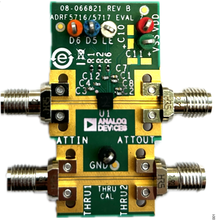
ADRF5717 硅数字衰减器(2 位、1 MHz 至 30 GHz)的评估
资料
最新评论
需要发起讨论吗? 没有关于 ADRF5717的相关讨论?是否需要发起讨论?
在论坛上发起讨论