MAX32625
量产具有基于FPU的微控制器(MCU)的超低功耗Arm Cortex-M4,具有512KB闪存和160KB SRAM
超低功耗Cortex-M4F理想用于新兴可穿戴医疗/健身产品
- 产品模型
- 8
产品详情
- 用于可穿戴设备的高效微控制器
- 内部振荡器工作频率高达96MHz
- 低功耗4MHz振荡器系统时钟选项,用于始终就绪的监测应用
- 512KB闪存(“L”版本为256KB)
- 160KB SRAM (“L”版本为128KB)
- 8KB指令缓存
- 1.2V核心电源电压
- 1.8V至3.3V I/O电源
- 可选3.3V ±5% USB电源
- 宽工作温度范围:-30°C至+85°C
- 电源管理最大程度延长电池应用的工作时间
- 从缓存执行代码时,有功电流为106µA/MHz
- 从闪存执行代码时,有功电流为49µA/MHz
- 唤醒至96MHz时钟或4MHz时钟
- 600nA低功耗模式(LP0)电流,使能RTC时
- 2.56µW超低功耗数据保持模式(LP1),5μs快速唤醒至96MHz时钟源
- 27µA/MHz低功耗模式(LP2)电流
- 最优外设组合,提高平台扩展性
- SPI执行(SPIX)引擎,以最小占位面积扩展内存
- 3个SPI主机、1个SPI从机
- 3个UART
- 多达2个I2C主机,1个I2C从机
- 1-Wire主机
- 全速USB 2.0器件,带内部收发器
- 16个脉冲序列(PWM)引擎
- 6个32位定时器和3个看门狗定时器
- 多达40个通用I/O引脚
- 10位Δ-Σ ADC,工作在7.8ksps
- AES-128、-192、-256
- RTC校准输出
- 可靠的内置硬件安全(仅限MAX32626),保证宝贵IP和数据的安全
- 信赖保护单元(TPU)提供ECDSA和模运算加速支持
- PRNG种子发生器
- 安全引导加载程序
DARWIN是一种全新品类的低功耗微控制器,专为迅猛发展的物联网(IoT)而生。该器件的智能性令人难以置信,拥有业界最大的存储器,以及可大规模扩展的存储器架构。得益于可穿戴级电源技术,器件可永远运行。器件也非常坚固,足以抵御最高级的网络攻击。DARWIN微控制器可运行您能想到的任何应用 — 其他微控制器则望尘莫及。
U系列微控制器非常适合注重功耗或性能的可穿戴和IoT应用。MAX32625/MAX32626具有Arm® Cortex®-M4 FPU CPU,具有高效信号处理功能、超低功耗,简单易用。
灵活的电源模式、智能PMU、动态时钟和功率门控最大程度提高性能、降低各项应用的功耗。内部96MHz振荡器提供高性能,4MHz振荡器最大程度延长电池寿命,适合要求常电监测的应用。
提供多个SPI、UART、I2C、1-Wire®主机接口和USB接口。带可选参考的四输入、10位ADC能够监测外部传感器。
所有版本均提供硬件AES引擎。MAX32626提供信赖保护单元(TPU),带有用于快速ECDSA的模运算加速器(MAA)、硬件PRNG熵发生器以及安全引导加载程序。MAX32625L提供较小的256kB闪存和128kB SRAM。
MAX32625用户指南
应用
- 健身监测器
- 便携式医疗设备
- 传感器集线器
- 运动手表
- 可穿戴医疗设备
参考资料
数据手册 2
可靠性数据 1
用户手册 7
应用笔记 9
设计笔记 1
技术文章 5
视频 3


电子书 1
模拟对话 5
ADI 始终高度重视提供符合最高质量和可靠性水平的产品。我们通过将质量和可靠性检查纳入产品和工艺设计的各个范围以及制造过程来实现这一目标。出货产品的“零缺陷”始终是我们的目标。查看我们的质量和可靠性计划和认证以了解更多信息。
| 产品型号 | 引脚/封装图-中文版 | 文档 | CAD 符号,脚注和 3D模型 |
|---|---|---|---|
| MAX32625ITK+ | Thin Quad Flatpack, No Leads | ||
| MAX32625ITK+T | Thin Quad Flatpack, No Leads | ||
| MAX32625ITKL+ | Thin Quad Flatpack, No Leads | ||
| MAX32625ITKL+T | Thin Quad Flatpack, No Leads | ||
| MAX32625IWY+ | 63-WLCSP-N/A | ||
| MAX32625IWY+T | 63-WLCSP-N/A | ||
| MAX32625IWYL+ | 63-WLCSP-N/A | ||
| MAX32625IWYL+T | 63-WLCSP-N/A |
这是最新版本的数据手册
软件资源
找不到您所需的软件或驱动?
申请驱动/软件硬件生态系统
工具及仿真模型
LTpowerCAD
LTpowerCAD中提供以下器件的设计工具:
软件开发 5
评估套件

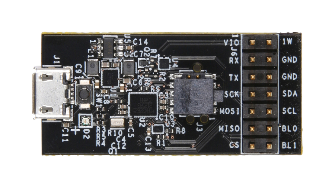
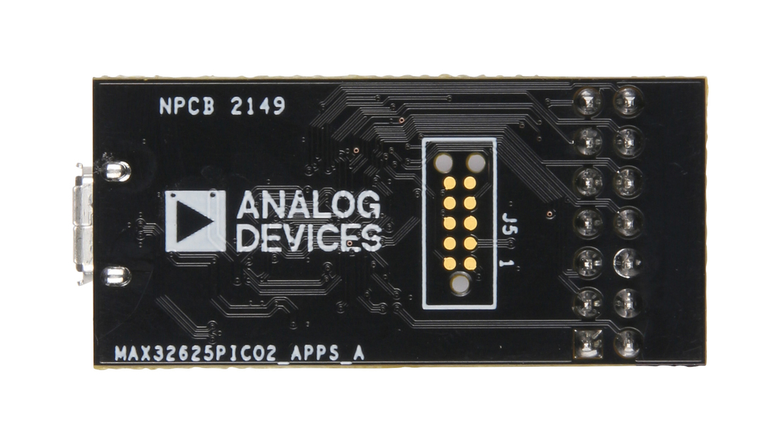
Evaluation Board for MAX32625, MAX14750, MAX20336
参考电路
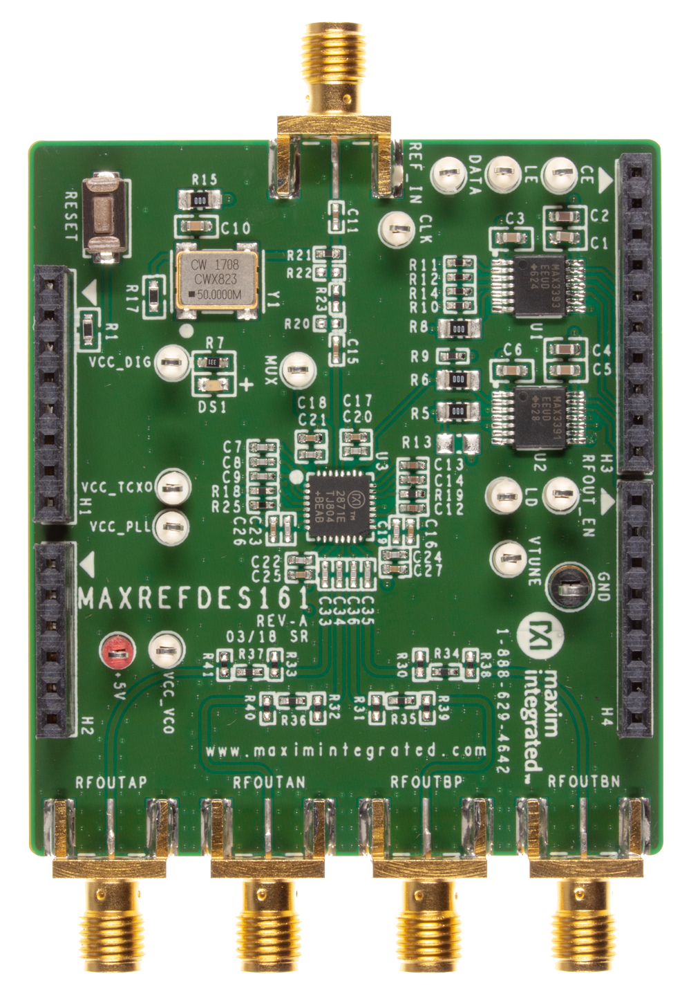
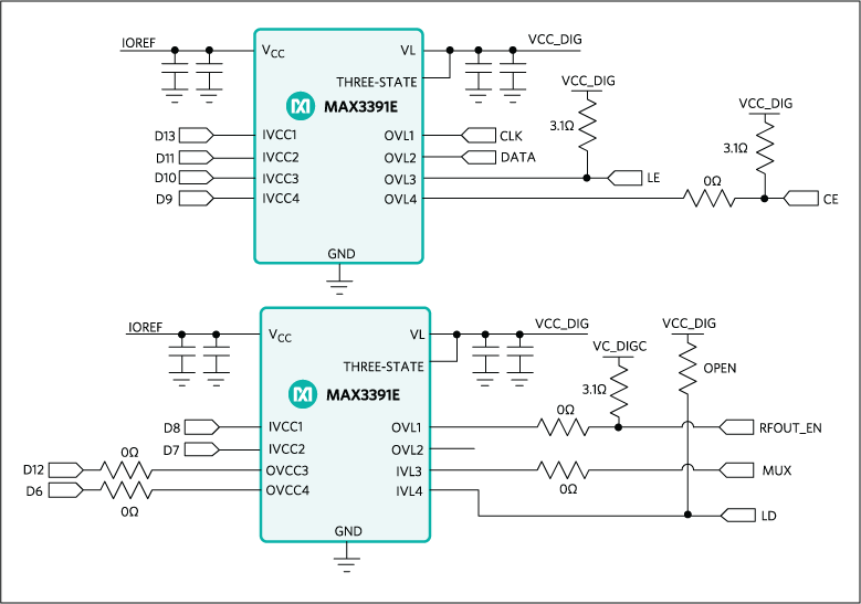
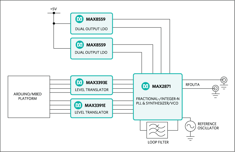
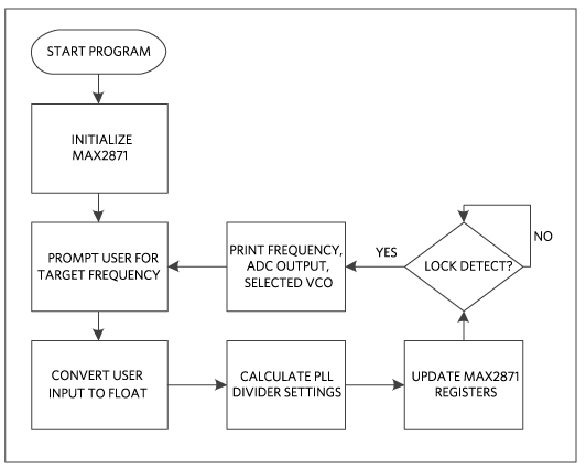
Frequency Synthesizer Shield with the MAX2871
使用部分
设计和集成工具
MAXREFDES183# Portable Precision Calibrator
使用部分
设计和集成工具
最新评论
需要发起讨论吗? 没有关于 MAX32625的相关讨论?是否需要发起讨论?
在EngineerZone®上发起讨论