ADATE324
ADATE324
推荐新设计使用1.6 GHz四通道集成DCL,内置VHH驱动功能、电平设置DAC和片内校准寄存器
- 产品模型
- 1
Viewing:
产品详情
- 2 种可选择的数据速率,高达 1.6 GHz 或 3.2 Gbps 的最大切换速率
- DCL 禁用模式(极低漏电流通常为 <10 nA)
- 电源和速度可编程(激活驱动器和比较器)
- 每通道低速功耗 1.025 W(案例 A)
- 每通道高速功耗 1.125 W(案例 B)
- 电压驱动器
- 具有高阻抗和反射钳位的 3 级驱动器
- 电压范围:–1.5 V 至 +4.5 V(+5 V 扩展范围)
- 精确调整的输出电阻
- 功能幅度 (VIH – VIL):0.05 V(最小值)至 6.0 V(最大值)
- 312.5 ps 最小脉冲宽度(1.0 V 可编程摆幅)
- 26 ps 确定性抖动,1.4 ps 随机抖动
- 比较器
- 差分和单端窗口模式
- 输入电压范围:–1.5 V 至 +4.5 V(+5 V 扩展范围)
- 130 ps ERT/EFT 正常窗口比较器 1.0 V,端接
- 有源负载:电流范围为 ±12 mA
- VHH 驱动
- 专用 VHH 输出引脚
- 电压范围:0.0 V 至 13.5 V
- 直流电平
- 完全集成的专用 16 位 DAC
- 具有自动加和乘功能的片内增益和失调校准寄存器
- 封装:9 mm × 9 mm、121 球芯片级封装球栅阵列 [CSP_BGA]
ADATE324是一款完整的单芯片、四通道自动测试设备(ATE)解决方案,用于执行驱动器、比较器和有源负载(DCL)的引脚电子(PE)功能。该器件还具有每芯片高电压(VHH)驱动能力以支持闪存测试应用。集成片内校准寄存器的专用16位数模转换器(DAC)可提供器件工作所需的所有直流电平。
电压驱动器提供三种有源状态:高、低和端接模式,以及一种高阻抗抑制状态。当驱动器未对此线路进行有源端接时,抑制状态以及集成动态箝位有利于传输线路反射的显著衰减。开路驱动能力为−1.5 V至+4.5 V,支持各种标准自动测试设备(ATE)和仪器仪表应用。
ADATE324可用作四通道、单端引脚电子通道或双通道差分通道。除了每通道高速窗口比较器之外,ADATE324提供两个适合差分ATE应用的可编程阈值差分比较器。
用于DCL功能的所有直流电平都由专用片内16位DAC产生。为了支持精确的编程电平,ADATE324还集成校准功能,可校正每个功能模块的增益和偏置误差。校正系数可以存储在片内,写入DAC的任何值都会利用适当的校正系数进行自动调整。
ADATE324使用串行可编程接口(SPI)总线对所有功能模块、DAC和片内校准常数进行编程。该器件还有一个片内温度传感器和过压/欠压故障箝位电路,用于监控和报告器件温度,以及工作期间可能发生的任何输出引脚电压故障。
欲了解有关ADATE324的更多信息,请联系 ADATE324@analog.com。
应用
- ATE
- 半导体和电路板测试系统
- 仪器仪表和表征设备
参考资料
ADI 始终高度重视提供符合最高质量和可靠性水平的产品。我们通过将质量和可靠性检查纳入产品和工艺设计的各个范围以及制造过程来实现这一目标。出货产品的“零缺陷”始终是我们的目标。查看我们的质量和可靠性计划和认证以了解更多信息。
| 产品型号 | 引脚/封装图-中文版 | 文档 | CAD 符号,脚注和 3D模型 |
|---|---|---|---|
| ADATE324KBCZ | CHIP SCALE BGA |
这是最新版本的数据手册
评估套件


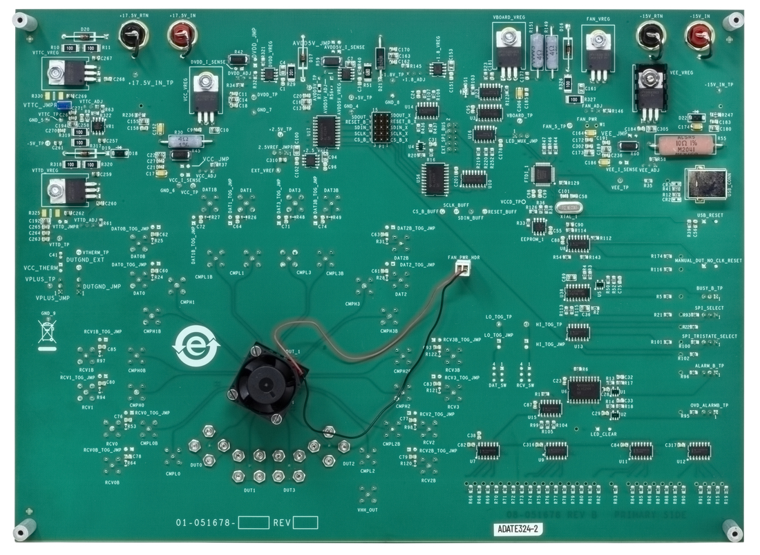
Evaluating the ADATE324 1.6 GHz Quad Integrated DCL with VHH Drive Capability, Level Setting DACs, and On-Chip Calibration Registers
最新评论
需要发起讨论吗? 没有关于 ADATE324的相关讨论?是否需要发起讨论?
在EngineerZone®上发起讨论